
Module Three: Queen Victoria Garden Pavilion
Pavilion Creation in Rhino & Grasshopper


Guidelines given for the project said the pavilion was to be no more than 5 x 5 x 5 meter in volume. Therefore, Grasshopper was used to set up a bounding box to assure the pavilion met the requirements.
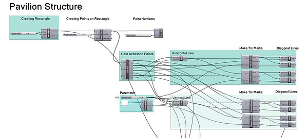


(Continues on
next image)
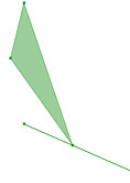
Dividing the ground into horizontal and vertical lines to be able to gain access to points. The parameter moves the lines in order to create the origami structure. Diagonal lines are tweaked and changed.

(Continues
here)

Mirroring the triangulated surface to create pavilion structure.
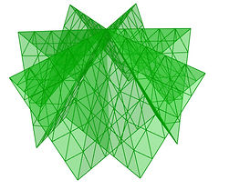
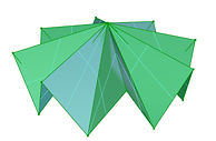


By using the triangulated panels created in Grasshopper, the roof structure was further developed as an individual element. Brep Join > Deconstruct Brep > Construct Mesh. Weaverbird Split Triangles Subdivision was used to add the triangulated surface panels to give the overall structure a more dynamic appearance.
Finalized Pavilion in Rendered View


Creating 1:25 Physical Model
Laser Cutting the Landscape
![Laser Cut For WIX [Converted].jpg](https://static.wixstatic.com/media/d88cf1_1d0e02e67c824c088a8280b72e4b4491~mv2_d_9727_10135_s_4_2.jpg/v1/fill/w_669,h_697,al_c,q_85,usm_0.66_1.00_0.01,enc_avif,quality_auto/Laser%20Cut%20For%20WIX%20%5BConverted%5D.jpg)
Creating the surrounding landscape for the pavilion by creating contours in Rhinoceros with the contour command and arranging the contours neatly on the given laser cut template. Several base contours were added to create a nice and thick base for the whole model to complement the thick material qualities of the 3D printed pavilion. The contours are arranged as close together with each other as possible to save material, laser cut time and cost. Six sheets of 1mm mountboard was used to create the topography.
3D Printing the Pavilion
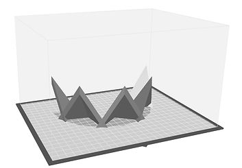

Creating the pavilion by 3D printing it at the university/s NExTLAB. The 3D printing process began with cutting the pavilion into sections (with the split command); one for the base (left image) and two for the roof with the triangulated surface panels (right image). Each section was imported into MakerBot > custom printing settings for Digital Design added > support structure was calculated.
Finalized 1:25 Physical Model


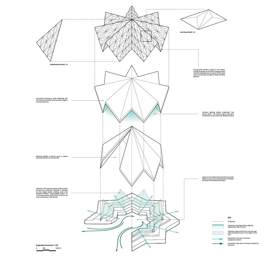
Exploded Isometric
Vignettes from Unreal Engine
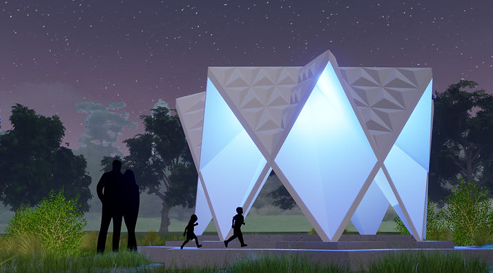
Vignette 01
Pavilion approached from the back at night, showing relationship to the surrounding landscape and the importance of the luminous light.

Vignette 02
View of pavilion in daylight, showing its various functions as well as the triangulated panels on the roof.

Vignette 03
Pavilion approached from the front at night, showing the various functions the pavilion can accommodate.
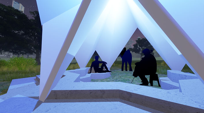
Vignette 04
View of the inside of the pavilion, to get a feel of the internal space.
Perspective
360 View of Interior Space
A
